Prototyping
Dec 2nd, 2013 by huntek3
Initial Mock-up
We began the project by looking at the old reflector frame and speaking to past cohorts of the Ghana Exchange Program. Speaking to these students allowed us to quickly examine the changes that would need to be made to the existing steel frame with regards to its rotation around the reactor chamber and tracking of the sun. We determined that the depth of the trough would need to be adjusted to move the axis of rotation closer to the frame.
[Insert Picture of Past Students]
Previously, the trough had been too shallow (i.e. the curve radius too large) which pushed the focal point six feet away from the reflector. This would mean that at midday when the reflector curve perpendicular to the ground, the reactor would be over nine feet in the air. This would create both accessibility and mechanical problems, as longer, more flexible tubing (to connect the reaction chamber with the cooking vessel) would be needed to accommodate for the large movements and more care would need to be taken to minimize the inevitable heat losses gained by the longer connection tube.
[Insert sketch of solar reflector]
We also spoke to Professor Jensen about possible reactor designs. Previously, the reactor was an open steel container. Much of the energy gains that were made, were lost to convective and conductive heat transfer, so the ink-water never reached temperatures above room temperature. From our discussions we determined that we would need to use either a flat-plat or evacuated tube reactor.
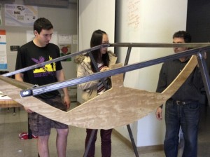
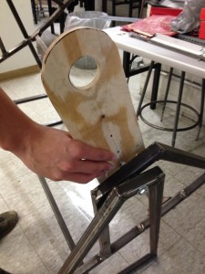
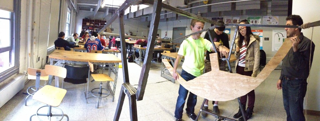
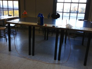
Plywood Model
A plywood model was constructed while we were waiting for the steel curves to be laser cut. The plywood model would have the same curve as the steel frame, but would be much faster to work with. We also constructed supports for the reactor out of plywood.
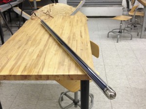
Copper Tube
The copper tube was initially filled with ethylene glycol and sealed on both ends. Epoxy was initially used as the sealant, and the idea was that the ethylene glycol would work as a transport fluid and allow heat exchange to occur more readily between the evacuated tube and the cooking vessel. The ends of the copper tube were crimped before being covered with epoxy and left to set for several days before testing.
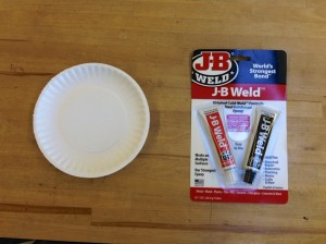
The copper tube wasn’t fully straightened, however, so the epoxy on one end cracked due to forces exerted when straightening the pipe. The epoxy used to seal the tube was rated for 400 F and 320 pounds/square inch, though it was too brittle to withstand any movement of the pipe. For this reason, we soldered the end of the copper tube instead of re-applying the epoxy. The soldered end of the tube would go into the evacuated glass chamber on the reactor and be exposed to high heat and pressure.
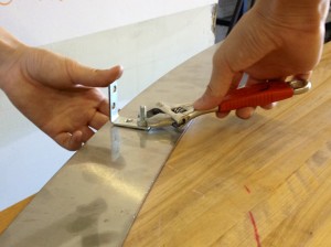
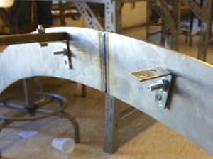
Stainless Steel Ribs
The stainless steel ribs, which form the shape of the reflector were laser cut in the Jonsson Science Center Machine shop. Holes were drilled into the curves to affix L-brackets which would be used to support the laminated reflector sheet. The L-brackets were secured using washers, nuts and bolts.
Solar Tracking
Lamination Methods
Lamination Rollers
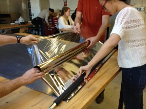
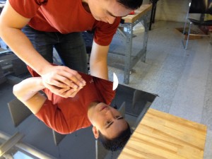
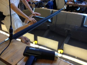
The lamination rollers available in Ghana are two rubber-steel rollers in 24” length, while the reflector film and surface to be laminated are in 48” length. The original trial of letting two person laminating separately with the two rollers did not work out, in that pressure was not distributed evenly from different person, which lead to wrinkles on the material.
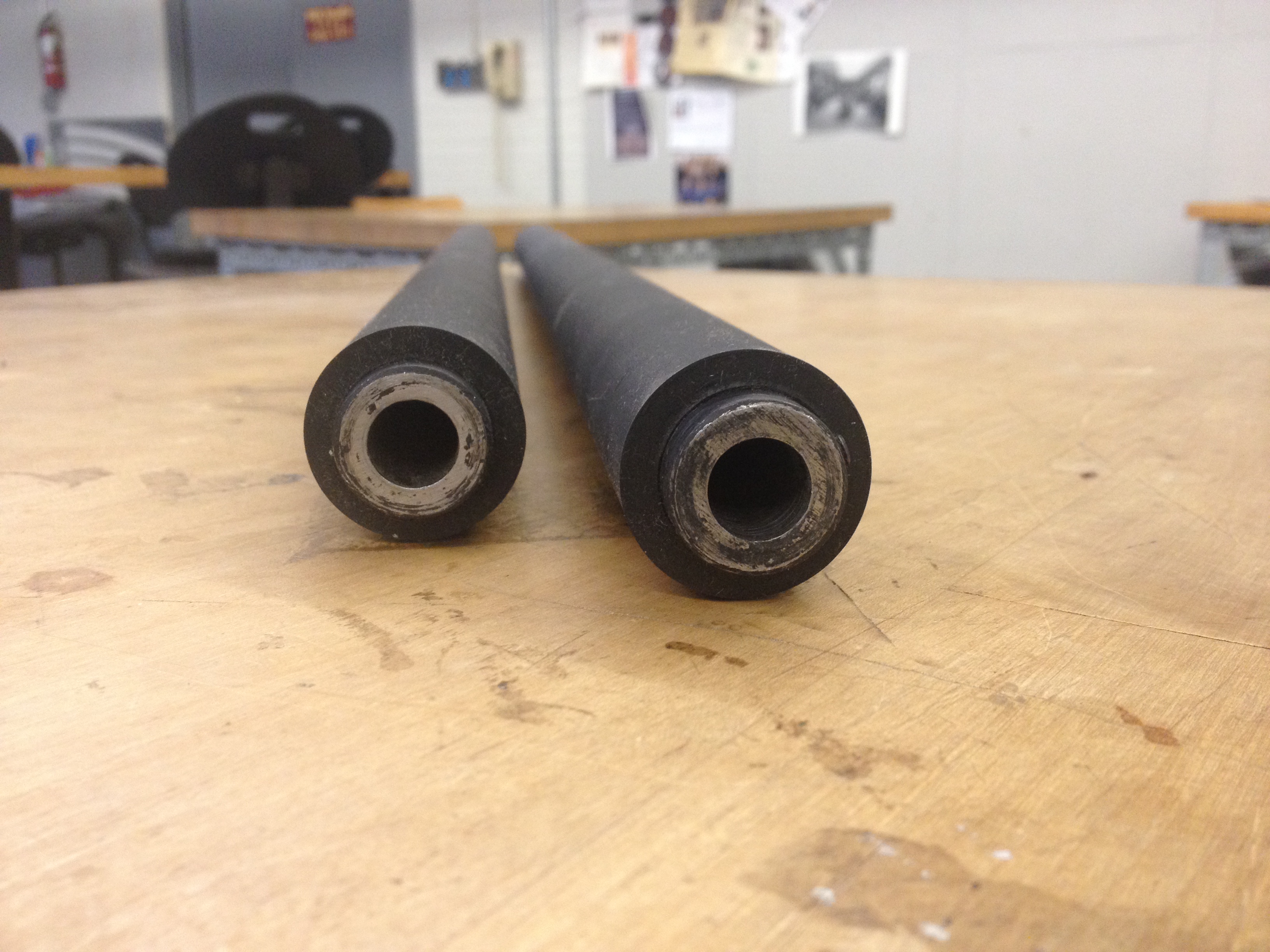
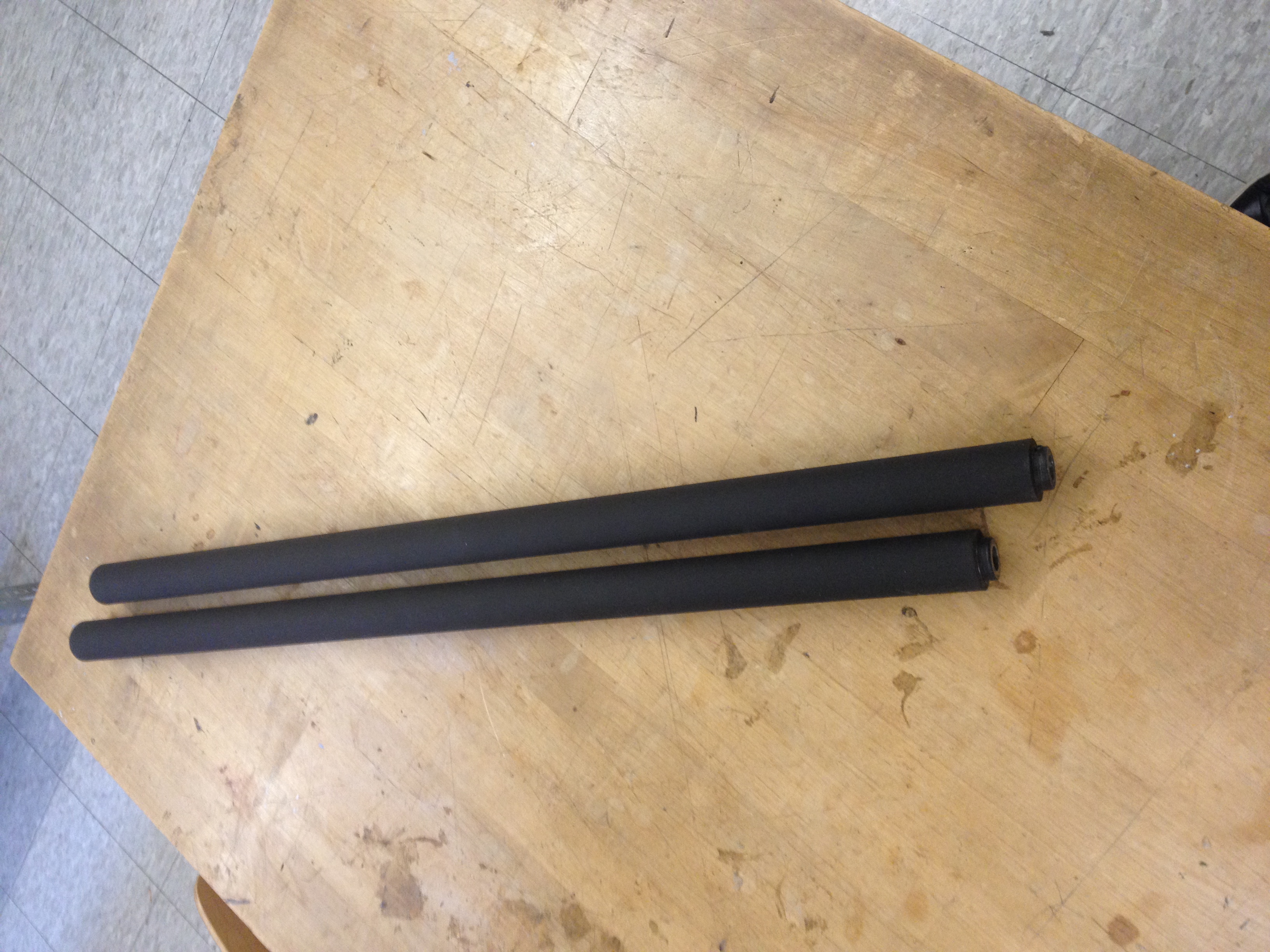
Figure 1&2: Original Lamination Rollers
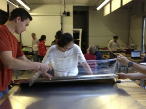
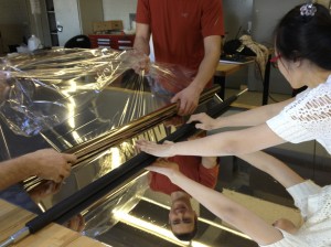
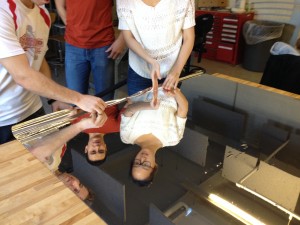
For the second iteration of the lamination rollers, we seek to join the two rollers together and let one person be in charge of rolling. Since the rollers are hollow inside, we purchased a piece of threaded rod of length xx- which is more than twice the length of one single roller, to fit inside the rollers from heads to tails, then tight the two ends with corresponding nuts, and thus, joined the rollers together. This solution works well in solving the lamination problems from the rollers’ aspect. However, the lamination process is more difficult to practice as we performed 3 trials.
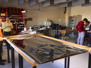
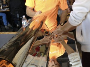
Lamination Process
This page has the following sub pages.