Hardware:
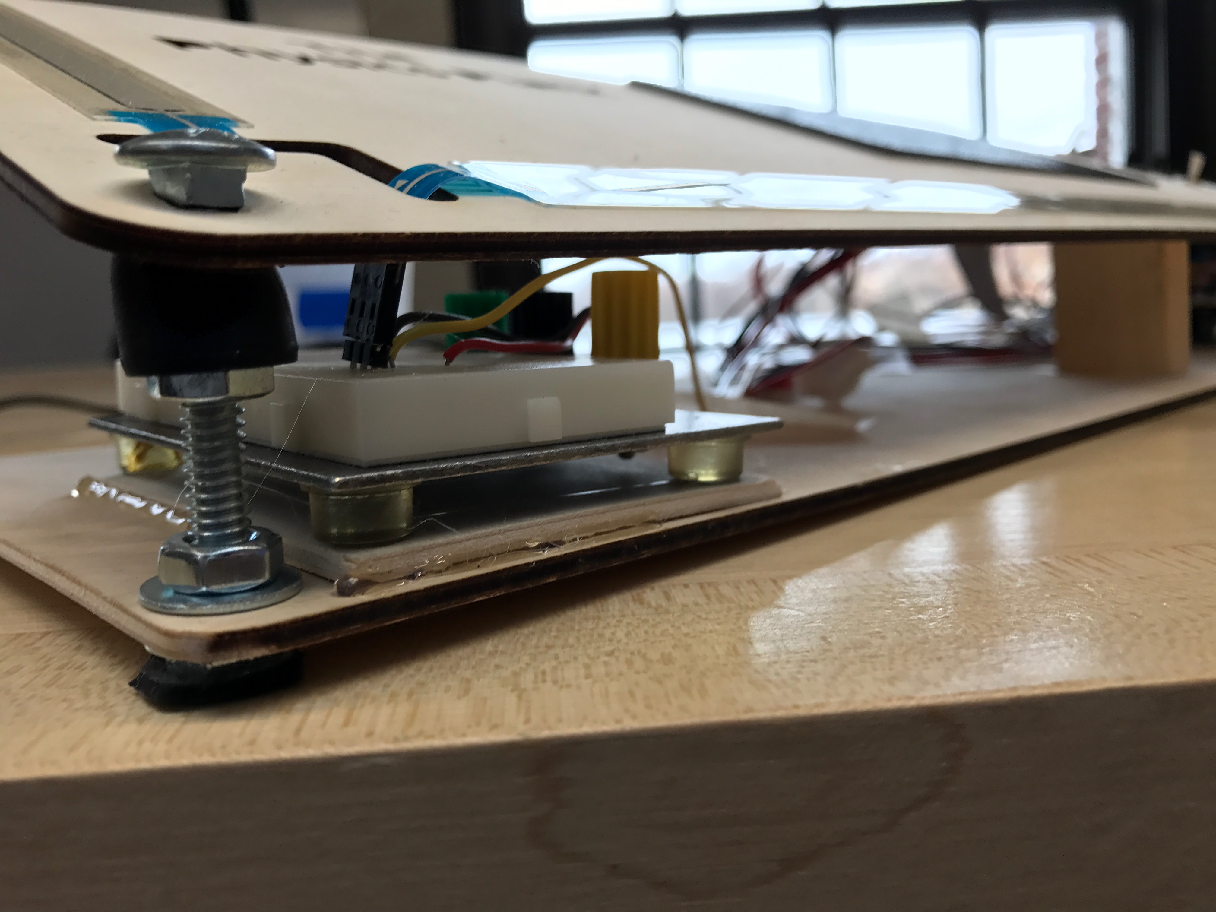
The hardware for the Physics Plank 2.0 was designed to give the user a clean and intuitive interface. The face of the plank is at a 25° angle from the horizontal allowing the users to just look down at it, rather than hover above it. The user can control the power and explore the modes using the switches neatly laid out to the right. Once powered the the users will be able to create their own waves using the ribbons running parallel to the left and bottom of the face centered along the LED matrix in the center. Having the plank at an angle allows for the electronics to be stored in the space directly bellow the board out of the way of the user. The sides are purposely kept open so the students using the board can be inspired by seeing the wiring that brings the board to life.
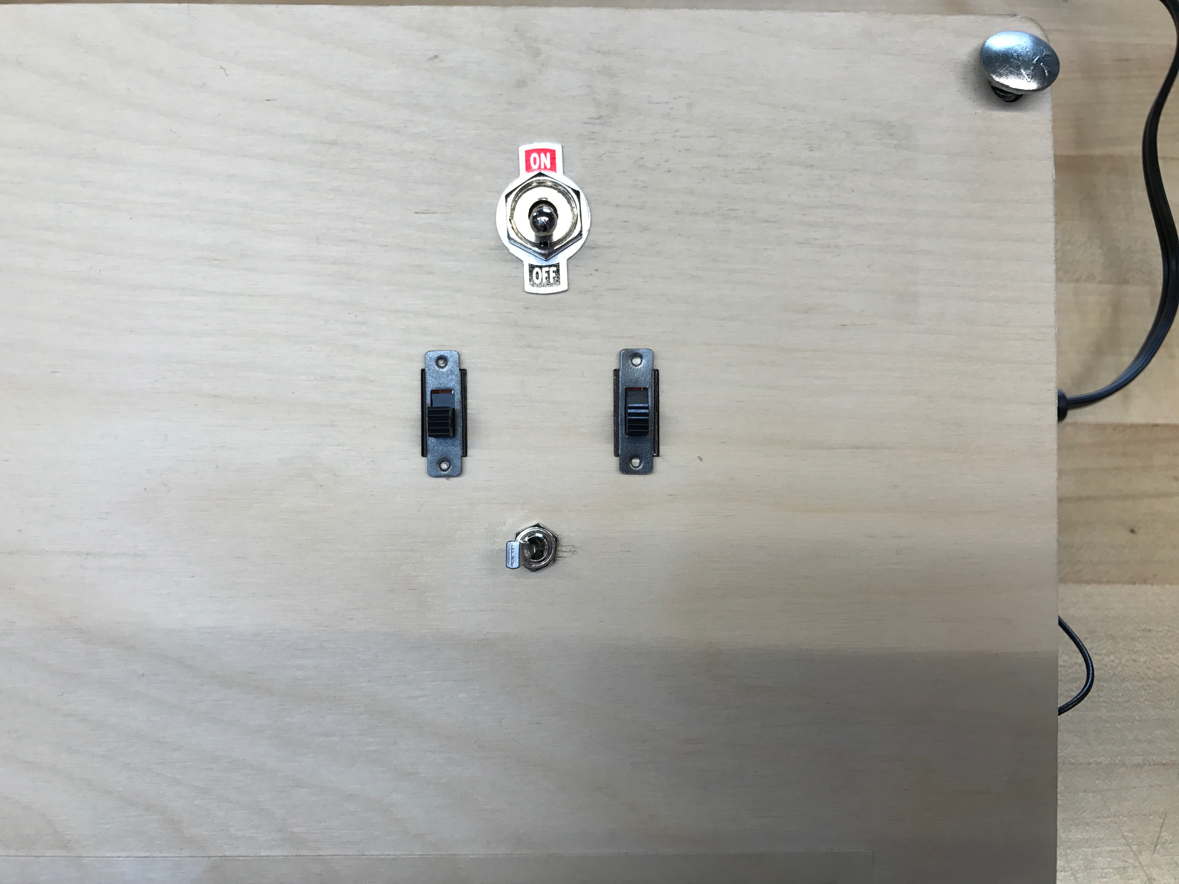
Although the black switches currently do not work, they will allow for greater functionality.
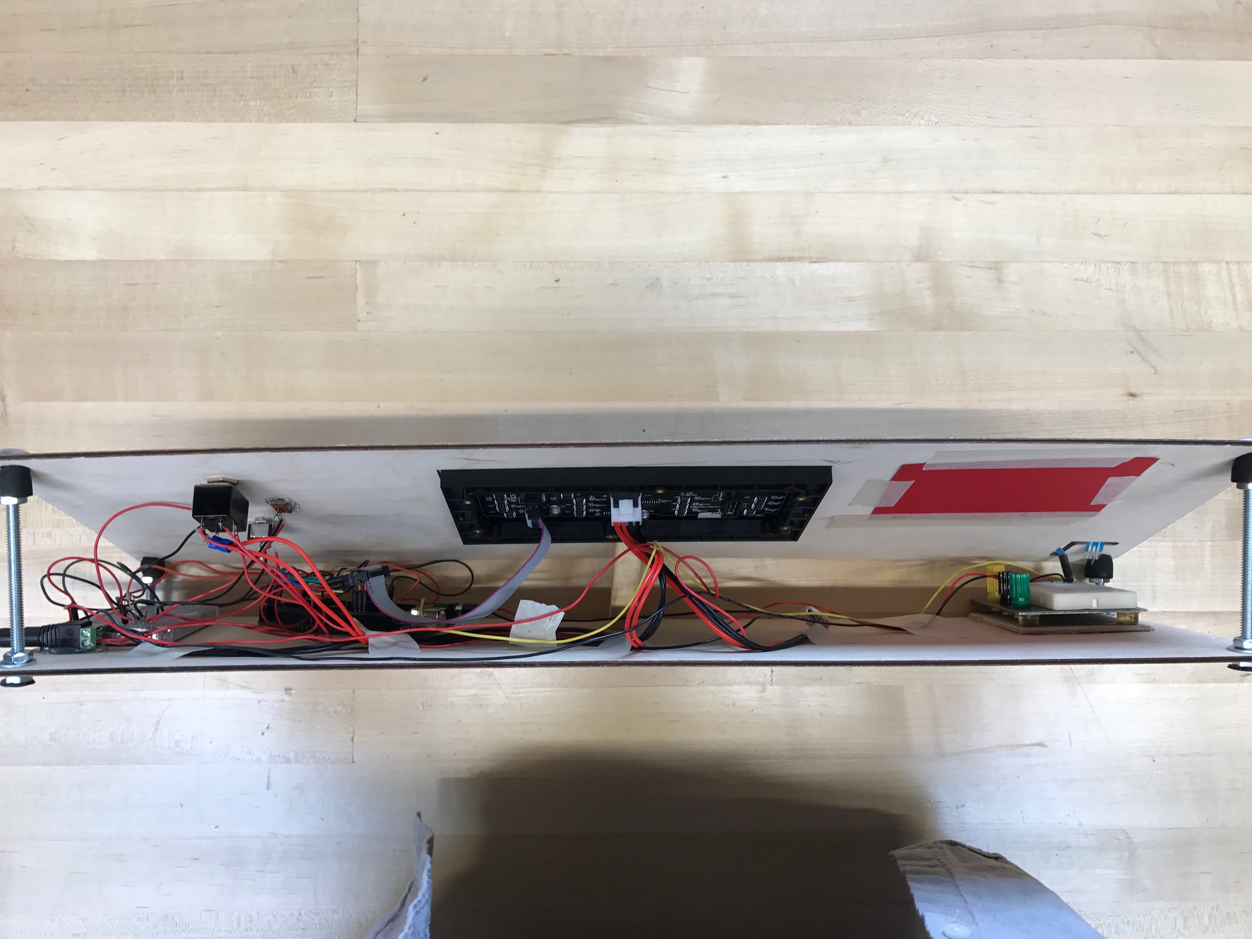
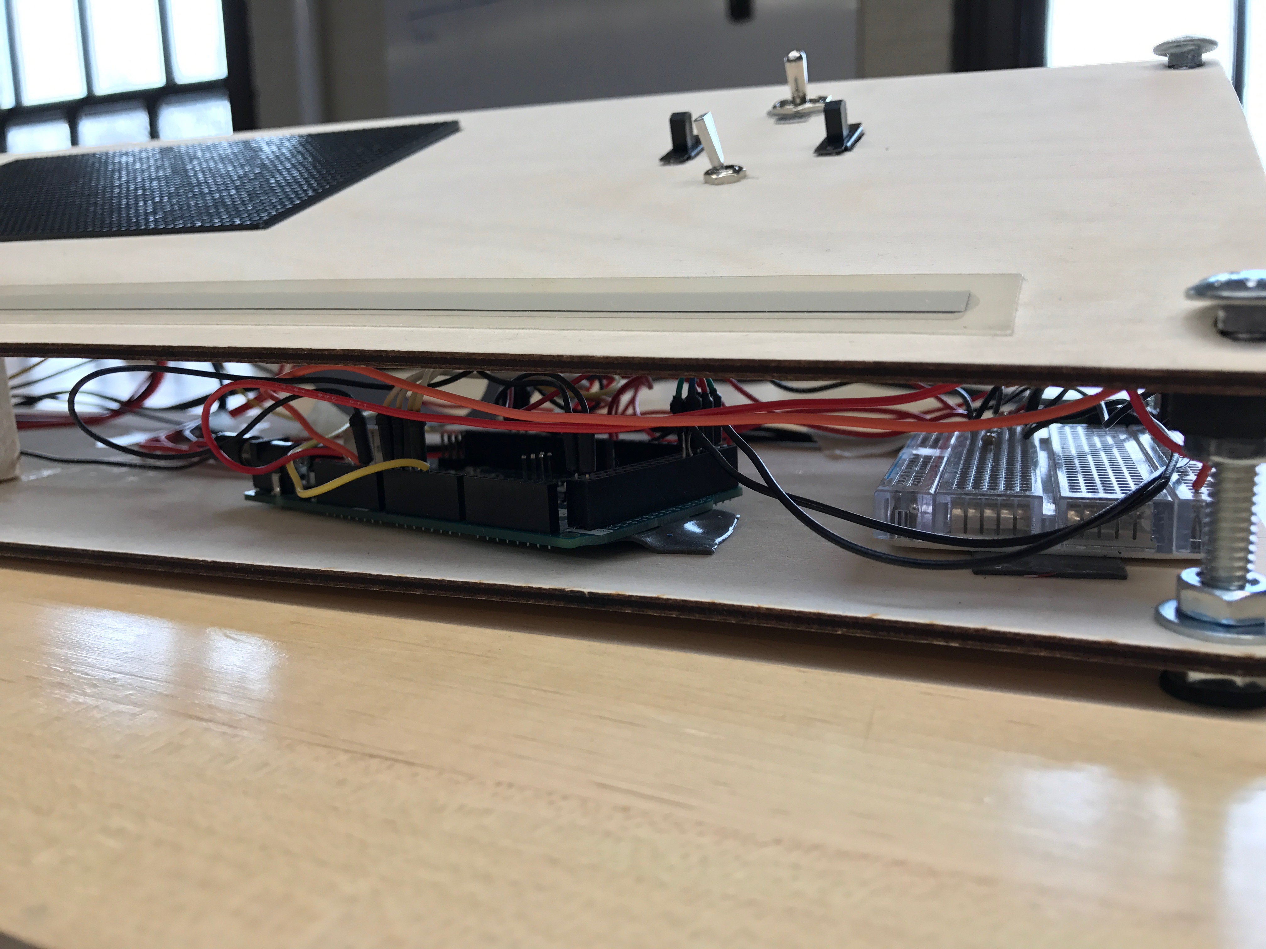
All the wiring is located below the top board away from where the user is swiping their hand.
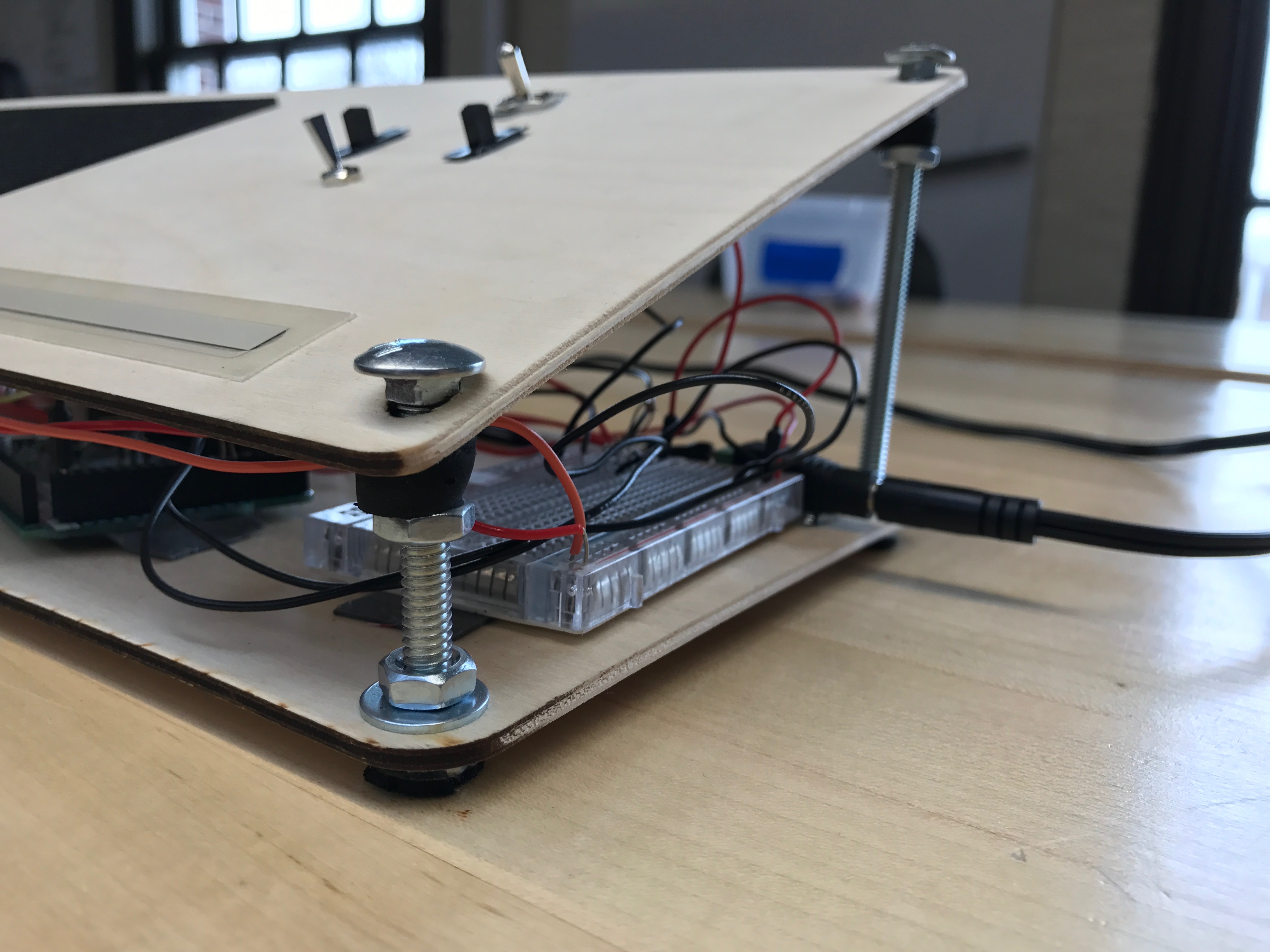
This bread board connects the switches the Arduino on the left. The power supply connector is behind the bread board.
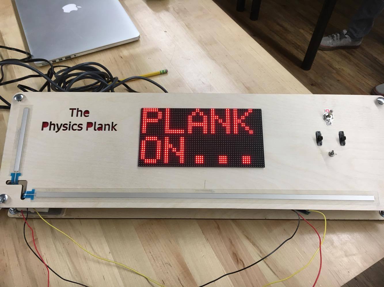
Initial display upon powering on
Software:
In Physics Plank 2.0 we decided that increased capability was necessary. We added three key features, the LED matrix, the live feedback Frequency mode, and the Frequency Game mode. When coding this we needed the LED matrix to turn on and instruct the user as to what to do next with the Physics Plank. From there depending on which mode the toggle switch was set too, the LED matrix would display that mode. We programmed two modes into the Physics Plank 2.0, a Live Frequency response and a Frequency Game. In the Live Frequency mode, the code would read the output from the sensor and print the wave created by the user in real time on the LED Matrix. It then also calculated the frequency of the wave created by counting the number of peaks over a certain amount of time. With the number of peaks counted the code would then change the color of the LED being turned on in the wave to that of the frequency being generate. The Frequency Game worked similarly but would ask the user to create waves for 3 seconds and then evaluate that 3 second period for the number of peaks in that time frame and turn the screen on with the color that corresponded to that frequency.