Phase 2: Medium Setup
Dec 4th, 2014 by bustaa2
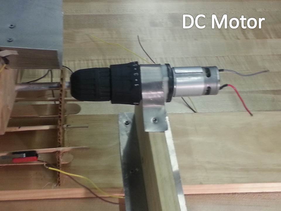
The second display was intended to show that the Arduino could drive a high amperage motor. The drill motor draws about 3A, which is significantly higher than what the Arduino can handle. As a result, we added some external circuitry to control the high-amp circuit.
- Amping up to DC
- Arduino signal must be put through a transistor
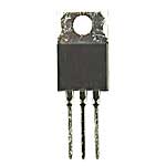
Tip 120 Transistor
- Be careful, they get hot.
- Make sure things are wired properly, if not they will catch on fire
Melted Bread Board
- Transistors can only control the motor in one direction. To drive the motor both ways, we needed an H-bridge. Larger setup
- This setup was designed to use a high-amp drill motor.
H-Bridge with Tip 120: http://trandi.wordpress.com/2011/04/20/my-first-h-bridge/

H-Bridge Clock Wise
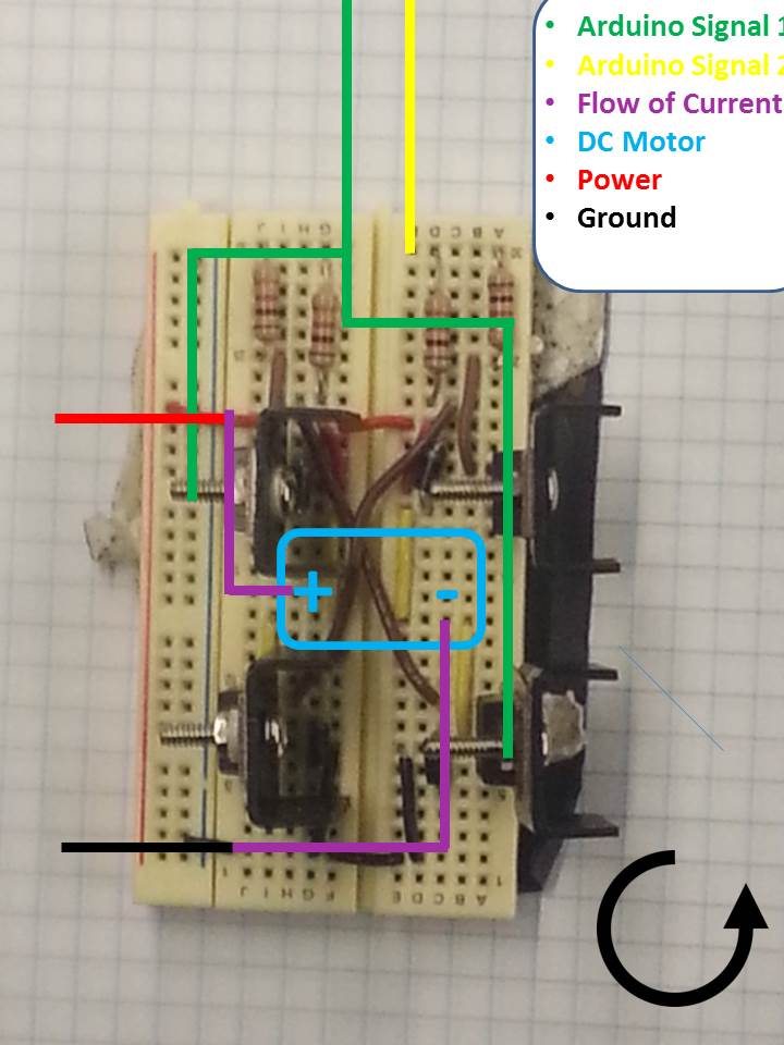
H-Bridge CounterClockwise
- Arduino control
- The motor is connected to pins 5 and 7 on the Arduino.
- To run motor forwards, set pin 5 on HIGH and pin 7 on LOW.
- To run backwards, 5 LOW 7 HIGH
- To turn off, set both LOW.
- NEVER HAVE BOTH PINS ON AT THE SAME TIME!!!!!!!!!!
- Do not need to give it specific position control – just tell it to go forward or backwards.
- The motor may run too fast for your setup. To control the amount of power sent to the motor, change the number in the “analogWrite funciton.”

- The program will take a number between 0 and 255 – 0 is the lowest voltage and 255 is the highest.
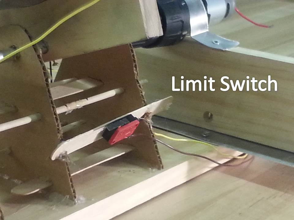
- For safety reasons, we added limit switches. If the motor turns too far, it will hit the switch and send a signal to the Arduino.
- The motor is connected to pins 5 and 7 on the Arduino.