Solar Tracker
Dec 5th, 2013 by parkes2
In order for the trough reflector design to be effective and efficient, it is necessary for a solar tracking system to be integrated into the design so that the reflector can gather a maximum level of sunlight even as the sun “moves across the sky”.
There are many existing systems that accomplish this task though the use of electronic control with sensors and a feedback system. Some are even weight driven but use electronic times to control the rate of decent of a weight. This is a very effective method for tracking the sun if there is a reliable source of power. We are designing our reflector for use in Ghana and around the world where electricity is not always readily available. Solar panels are often a good alternative and using a backup battery system when the sun goes behind the clouds makes it more effective but in Ghana, things like this will be stolen and reused for something else. We have to consider appropriate technologies for Ghana.
These were two separate tracking system iterations built by the summer 2013 exchange group. These servo driven systems both failed to provide adequate torque to the frame and more importantly yet completely overlooked in the design, these methods didn’t move the reflector at a constant rate that is needed.
Our group and others before us have all determined that a non-electric, mechanical heliostat will have the best chances of success.
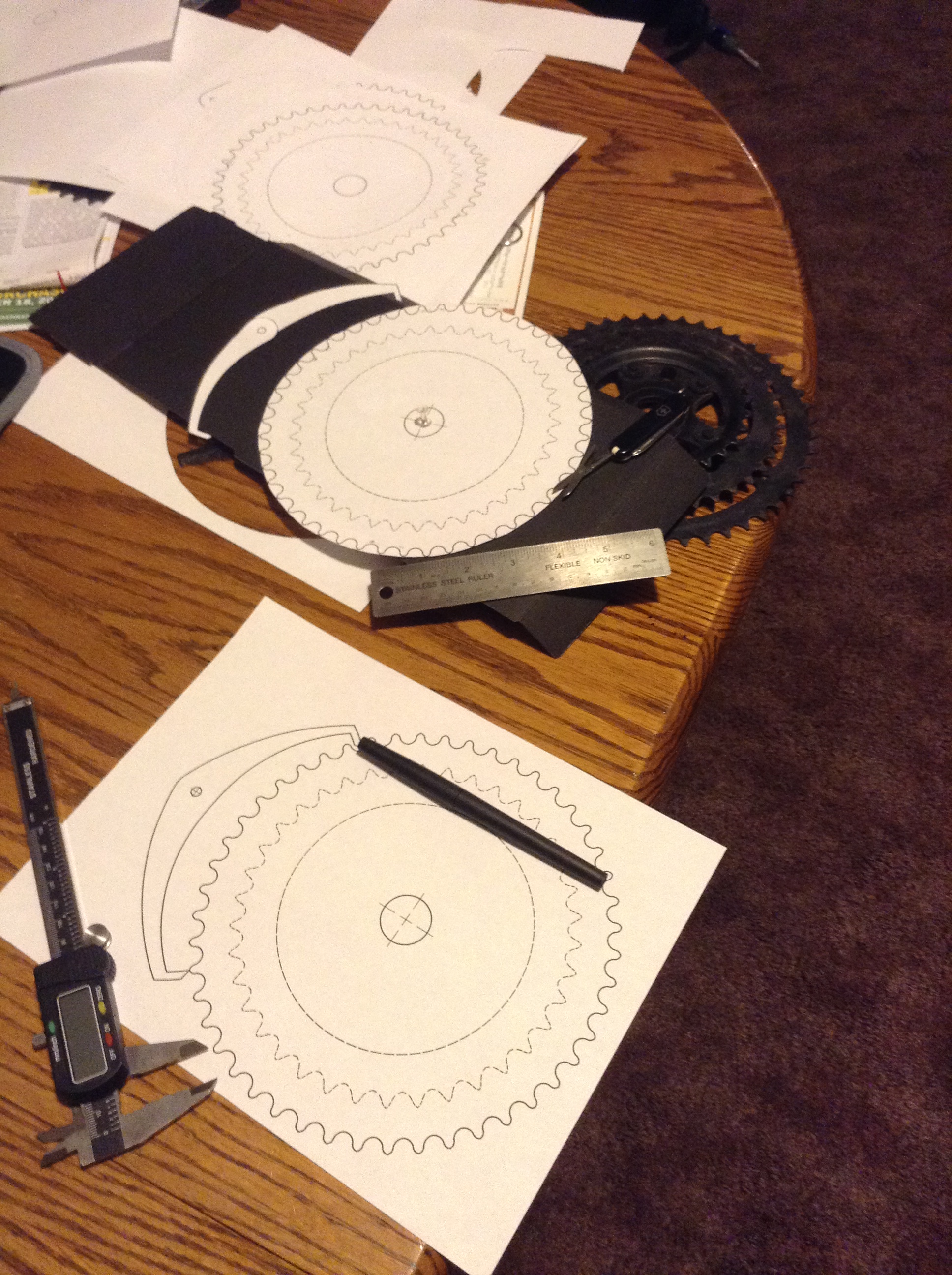
Design process and iterations of the escapement wheal. Struggled to make a bike part work to this.

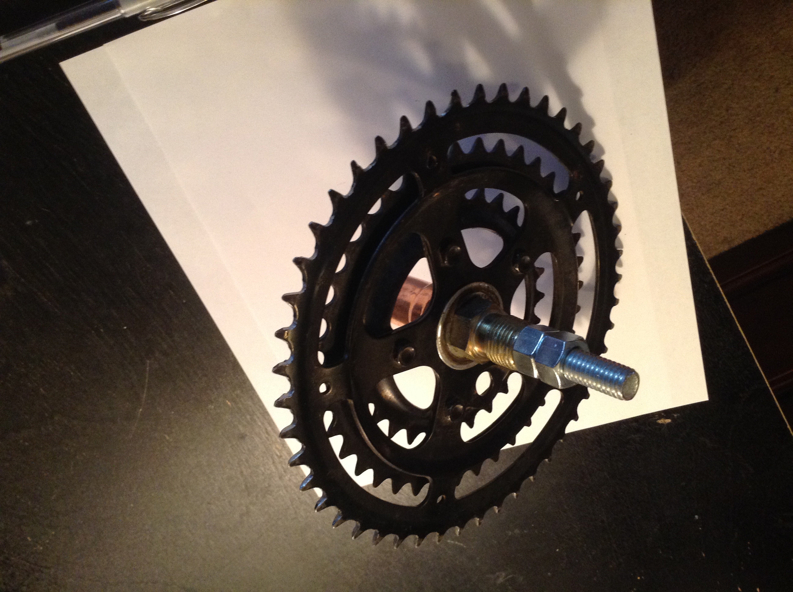
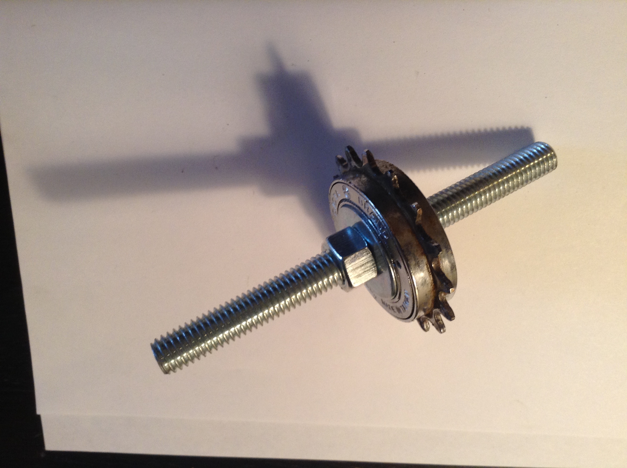
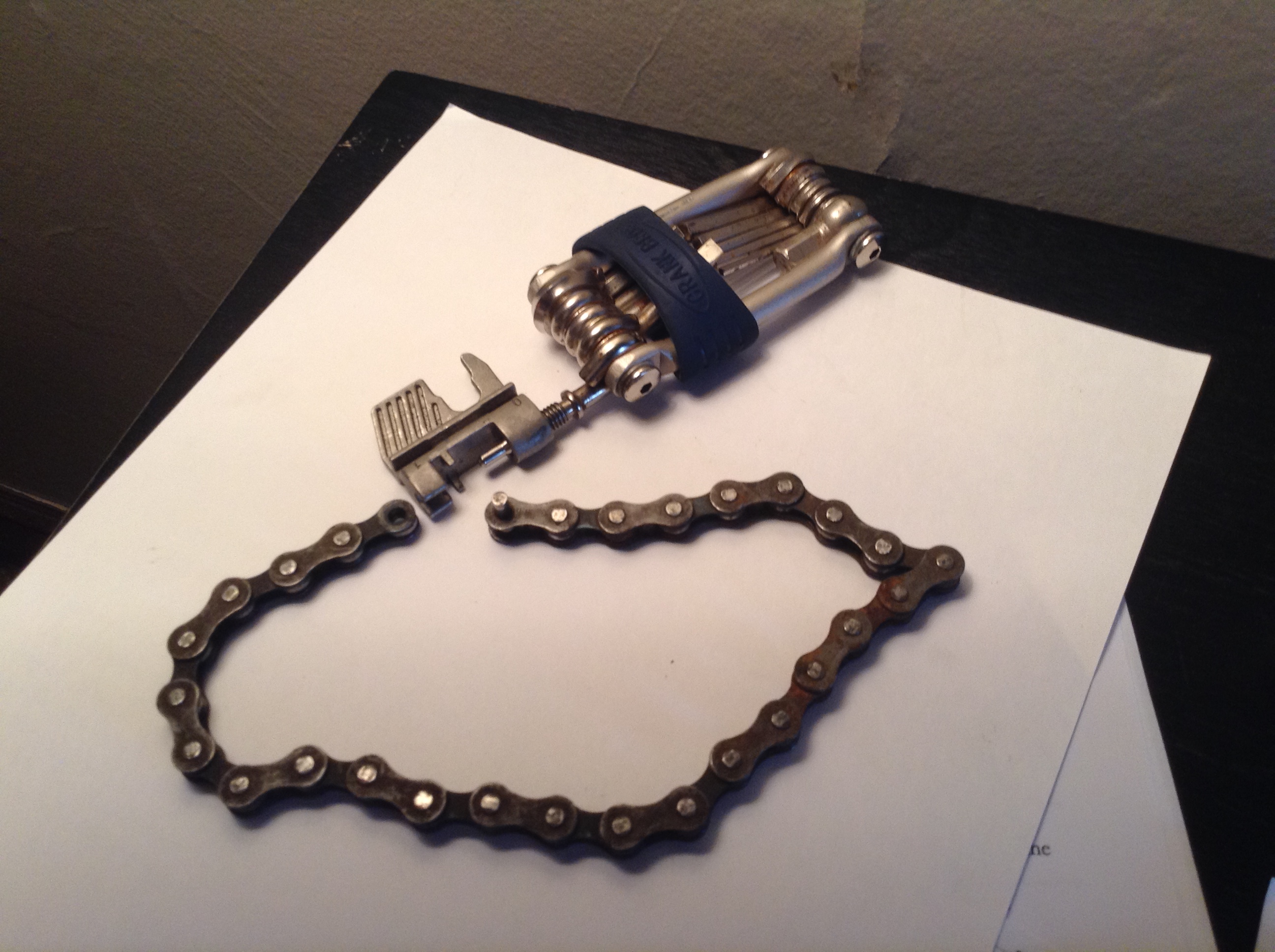

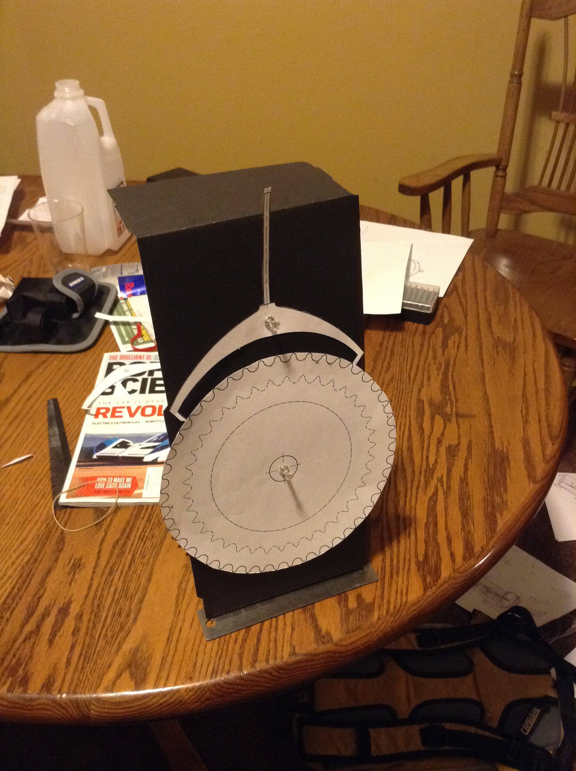
Building a semi-functional prototype as proof of concept to continue with the bike gear. The tooth geometry had to be slightly altered to prevent slipping from non-perpendicular surface force between the anchor and escapement wheel. Final design would use a different gear ratio.

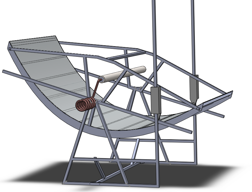
A proposed upgrade to the current frame design enables a constant force to be applied in a confined space without a pulley system.
This assumes that the center of gravity is able to be placed along the axis of rotation.
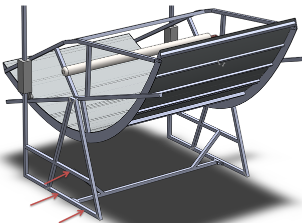

The red arrows indicate where the heliostat will be attached to the frame. The image above is a conceptual model of the mechanical heliostat.
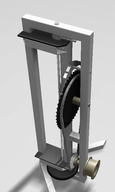
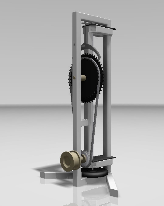
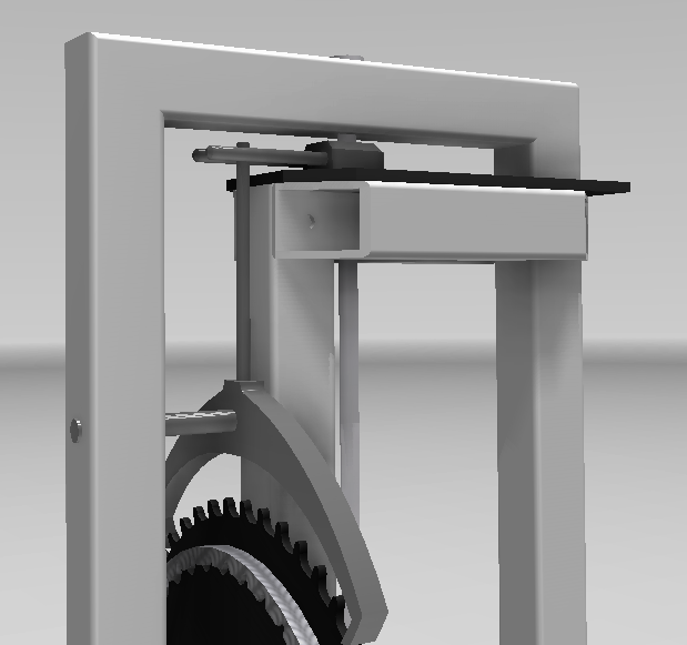
Inner structure