Codes and Hardware
Dec 7th, 2014 by bustaa2
Simple Heliostat: This setup is designed to take a reading every 5 seconds and send the output to your laptop.
- Photoresistors: Wire the photo resistors as shown below.
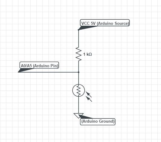
- Servo – The servo has three wires
- Red – 5V power in Arduino
- Black – Arduino Ground
- White – Pin 4 on Arduino
The code is shown below: Note: There are a few variables that you can plan with (they are shown in blue):
- Sensitivity: Will control how much light interference will be blocked out. A higher number will filter out more interference.
- Delay: Will affect the time in between readings as well as the amount of time between servo adjustments.
/*
Arren Bustamante
Heliostat: This program is designed to turn a servo to point towards a light source
It will spend about a second aligning the heliostat with the sun’s position and then turn off the servo motor.
Every 5 seconds it will loop the process.
*/
#include<Servo.h> //include necessary files
Servo myservo; //name servo “myservo”
int pos = 90; //Define “pos” as the angle of the motor
int Right = A0; // Input pin for right sensor
int Left = A5; //Input pin for left sensor
int RightValue = 0; // variable to store the value coming from the sensor
int LeftValue = 0;
int sensitivity = 50; /* For in doors, set the value around 50. This will filter out any weaker light sources in the room.
For outdoors, set around 5. There will be less interferance outdoors since the sun is significantly
brighter than light interference. */
const int chipSelect = 10; //Ues pin 10 to write to SD card.
void setup()
{
Serial.begin(9600); //Begin serial command to enable sensor readings
while (!Serial)
{
; // wait for serial port to connect. Needed for Leonardo only
}
myservo.attach(4); //Servo is connected to pin 4
myservo.write(pos); //set servo to default position (90 deg) when program starts up
}
void loop()
{
for(unsigned char i = 0; i <20; i++) //The number of loops controls how long the heliostat spends lining up with the sun before recording the position.
{
myservo.attach(4); //turns on the servo (note that servo is drawing power even if it is not moving)
RightValue = analogRead(Right); //Takes an analog reading of the right sensor and stores it to the variable RightValue
LeftValue = analogRead(Left);
if(LeftValue < RightValue) //Checks if the Right side is under more light than the left side.
{
if((LeftValue < RightValue) && (LeftValue + sensitivity < RightValue)) /*Checks to see if the right side is significantly brighter than the left side by adding a buffer to the
left side. This is used to filter out both light interference and inconsistencies in the analog readings.*/
{
pos = pos + 1; //incriments position variable 1 degree per 50 ms.
myservo.write(pos); //sets the servo motor to that position.
delay(50); //waits 50ms.
}
}
else if((LeftValue > RightValue) && (LeftValue > RightValue +sensitivity)) /*If the Right side is not brighter than the left side,
that means that the Left side must be brighter than the right side
(or that both sides are equal.) If the left side is brighter than the right side
and the left side is greater than the right side plus the buffer, then this will be viewed
as a “significant difference and will move the servo.”*/
{
pos = pos – 1; //deincriments servo position variable.
myservo.write(pos);
delay(50);
}
if (pos <= 20) //If position is less than 20 deg, set servo back to 20 deg. This prevents the servo from turning too far and breaking the rig.
{
pos = 20;
}
if (pos >= 160) //If the position is more than 160 degrees, set back to 160 degrees.
{
pos = 160;
}
}
Serial.print(“\r\n\t”); //Creates a new line on the serial link.
Serial.print(LeftValue); //prints the analog reading of the left sensor
Serial.print(“\t”); //creates a tab on the serial link
Serial.print(RightValue);
Serial.print(“\t”);
Serial.print(pos); //print servo position
myservo.detach(); //Turns the servo completely off in order to save power.
delay(5000); //Wait 5 seconds(Change this value if you to change the time between position changes
Serial.print(“\r\n mark”);
myservo.attach(9); //Turns servo back on.
}
Long term test for heliostat: Connect the SD reader to the Arduino. Wire everything to the SD reader as you would to the Arduino in the previous description.
Like in the one above, you may change the lines in blue to control the sensitivity and the delay time (note that delay time is in milliseconds).
/*
Arren Bustamante
Heliostat: This program is designed to turn a servo to point towards a light source
It will spend about a second aligning the heliostat with the sun’s position and then turn off the servo motor.
After this, it will record the luminosity of each sensor as well as the position of the servo to an SD card.
Every 10 minutes it will loop the process.
*/
#include<Servo.h> //include necessary files
#include <SD.h>
Servo myservo; //name servo “myservo”
int pos = 90; //Define “pos” as the angle of the motor
int Right = A0; // Input pin for right sensor
int Left = A5; //Input pin for left sensor
int RightValue = 0; // variable to store the value coming from the sensor
int LeftValue = 0;
int sensitivity = 10; /* For in doors, set the value around 50. This will filter out any weaker light sources in the room.
For outdoors, set around 5. There will be less interferance outdoors since the sun is significantly
brighter than light interference. */
const int chipSelect = 10; //Ues pin 10 to write to SD card.
void setup()
{
Serial.begin(9600); //Begin serial command to enable sensor readings
while (!Serial)
{
; // wait for serial port to connect. Needed for Leonardo only
}
myservo.attach(4); //Servo is connected to pin 4
myservo.write(pos); //set servo to default position (90 deg) when program starts up
SD_initialization(); //Initializes SD card function.
}
void loop()
{
for(unsigned char i = 0; i <20; i++) //The number of loops controls how long the heliostat spends lining up with the sun before recording the position.
{
myservo.attach(4); //turns on the servo (note that servo is drawing power even if it is not moving)
RightValue = analogRead(Right); //Takes an analog reading of the right sensor and stores it to the variable RightValue
LeftValue = analogRead(Left);
if(LeftValue < RightValue) //Checks if the Right side is under more light than the left side.
{
if((LeftValue < RightValue) && (LeftValue + sensitivity < RightValue)) /*Checks to see if the right side is significantly brighter than the left side by adding a buffer to the
left side. This is used to filter out both light interference and inconsistencies in the analog readings.*/
{
pos = pos + 1; //incriments position variable 1 degree per 50 ms.
myservo.write(pos); //sets the servo motor to that position.
delay(50); //waits 50ms.
}
}
else if((LeftValue > RightValue) && (LeftValue > RightValue +sensitivity)) /*If the Right side is not brighter than the left side,
that means that the Left side must be brighter than the right side
(or that both sides are equal.) If the left side is brighter than the right side
and the left side is greater than the right side plus the buffer, then this will be viewed
as a “significant difference and will move the servo.”*/
{
pos = pos – 1; //deincriments servo position variable.
myservo.write(pos);
delay(50);
}
if (pos <= 20) //If position is less than 20 deg, set servo back to 20 deg. This prevents the servo from turning too far and breaking the rig.
{
pos = 20;
}
if (pos >= 160) //If the position is more than 160 degrees, set back to 160 degrees.
{
pos = 160;
}
}
Serial.print(“\r\n\t”); //Creates a new line on the serial link.
Serial.print(LeftValue); //prints the analog reading of the left sensor
Serial.print(“\t”); //creates a tab on the serial link
Serial.print(RightValue);
Serial.print(“\t”);
Serial.print(pos); //print servo position
SD_write(LeftValue, RightValue, pos); //Saves these three variables to the SD card.
myservo.detach(); //Turns the servo completely off in order to save power.
delay(100000); //Wait 10 mins (Change this value if you to change the time between position changes
Serial.print(“\r\n mark”);
myservo.attach(9); //Turns servo back on.
}
void SD_initialization() //All of this code is coppied from the Arduio website. Don’t change it. It works.
{
Serial.print(“Initializing SD card…”);
// make sure that the default chip select pin is set to
// output, even if you don’t use it:
pinMode(10, OUTPUT);
// see if the card is present and can be initialized:
if (!SD.begin(chipSelect)) {
Serial.println(“Card failed, or not present”);
// don’t do anything more:
return;
}
Serial.println(“card initialized.”);
}
void SD_write(int LeftValue, int RightValue, int pos) //This is the function that will write to the SD card and is called in the main loop.
{
// open the file. note that only one file can be open at a time,
// so you have to close this one before opening another.
File dataFile = SD.open(“datalog.txt”, FILE_WRITE);
// if the file is available, write to it:
if (dataFile) {
dataFile.print(“\r\n\t”); //print value of left sensor
dataFile.print(LeftValue);
dataFile.print(“\t”);
dataFile.print(RightValue); //pirnt value of right sensor
dataFile.print(“\t”);
dataFile.print(pos); //print the position of the servo.
dataFile.close();
delay(2);
}
// if the file isn’t open, pop up an error:
else { //Tells the Arduino to complain if there is no SD card.
Serial.println(“error opening datalog.txt”);
}
}
H-Bridge Test – Before you connect your motor to your heliostat, you might want to make sure that you can drive it from your H-bridge.
- You can buy an H-bridge like this one
- http://www.miniinthebox.com/l9110-dual-channel-h-bridge-motor-driver-module-for-arduino_p903443.html?currency=USD&litb_from=paid_adwords_shopping&gclid=CLW9o9r9tMICFURo7AodNlkArw
- Or you can build your own like this one
- http://trandi.wordpress.com/2011/04/20/my-first-h-bridge/
- Be careful when building it. In order for it to operate properly, you must connect it to a 12V power source. If there are shorts present, it will start smoking/catch on fire. Be careful.
- Either way, you will have two signal wires going from the H-Bridge to the Arduino. They will connect to pins 5 and 7,
Here is the code to run the motor:
int forward = 5; //This pin will drive the motor forward and connects to the H-bridge
int reverse = 7; //This pin will drive it backwards.
void setup()
{
pinMode(forward, OUTPUT);
pinMode(reverse, OUTPUT);
}
void loop()
{
digitalWrite(forward, LOW); //Motor is off
digitalWrite(reverse, LOW);
delay(1000); //Wait one second
digitalWrite(forward, HIGH); //Turn motor on forward
digitalWrite(reverse, LOW);
delay(1000); //wait one second
digitalWrite(forward, LOW); //Turn motor off
digitalWrite(reverse, LOW);
delay(1000); //Wait one second
digitalWrite(forward, LOW); //Turn motor in reverse
digitalWrite(reverse, HIGH);
delay(1000); //Wait one second.
}
Final Prototype: We have modified the first code (heliostat tracker) so that it will be driven by the DC motor. Theoretically, this should be the code used in the prototype. Unfortunately, we did not have time to test this.
Here is how to wire it:
- Photoresistors – A0 and A5 (diagram shown previously)
- H-Bridge signals – 5 and 7 (diagram shown previously)
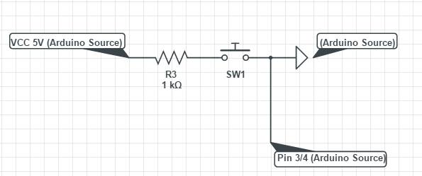
- Limit switches – one on pin 3 and one on pin 4 wired as such
The code is shown below. To adjust the voltage given to the motors, change the numbers in blue:
int forward = 5; //Forward motor direction is on pn 5
int reverse = 7; //Reverse motor direction is pin 7.
int Right = A0; //Right photosensor on A0
int Left = A5;
int RightValue = 0; //Variable which stores the value that is read by the right sensor.
int LeftValue = 0;
int sensitivity = 10; //Setting that adjust the buffer value to screen out interferance (around 10 for outdoors and around 50 for indoors.)
int AV_speed = 170; //Controlls the voltage sent to the Motors in the Analog Read function.
boolean RightLimit = 0; //The value of the right limit switch (on or off)
boolean LeftLimit = 0;
// Right Bumper on 3, and left bumper on 4
void setup()
{
Serial.begin(9600);
pinMode(forward, OUTPUT); //Set ouptus and inputs
pinMode(reverse, OUTPUT);
pinMode(3, INPUT);
pinMode(4, INPUT);
}
void loop()
{
RightValue = analogRead(Right); //Assign the reading from the Right sensor to the variable “RightValue”
LeftValue = analogRead(Left);
RightLimit = digitalRead(3); //Stores the state of the limit switch into the variable “Right Limit”
LeftLimit = digitalRead (4);
if(LeftValue < RightValue) //Checks to see if the Right photosensor is under more light than the left one.
{
if((LeftValue< RightValue) && (LeftValue + sensitivity < RightValue)) //Checks if the right side is brighter and it is brighter than the left side plus a buffer value
{
analogWrite(forward, 170); //Run motor forwards
analogWrite(reverse, 0);
delay(50);
}
}
else if((LeftValue > RightValue) && (LeftValue > RightValue + sensitivity)) //This is pretty much the same as the last if statement, just for the other side.
{
analogWrite(forward, 0);
analogWrite(reverse, 170);
delay(50);
}
}
if(RightLimit || LeftLimit) /*If either of the limit switches are triggered, stop the motor. Note that if the motor is stopped, the heliostat might be resting on the limit
switch and keep the program in this if statment. You might want to later add some code that will nudge the motor off the switch when the limit
switch is triggered.*/
{
analogWrite(forward, 0);
analogWrite(reverse, 0);
}
else //If none of these happen, then turn off the motor. This acts as a safety measure to make sure that both pins will not be on at the same time.
{
analogWrite(forward, 0);
analogWrite(reverse, 0);
}